
ITRON DEVELOPER PROGRAM
Develop with Itron,
unlock your potential.
Discover a new world of capabilities and create innovative solutions — the possibilities are endless.
Distributed Intelligence
DI developers at Itron create and implement innovative solutions using the distributed intelligence platform, enabling real-time visibility and control for efficient management of low- and medium- voltage electric grids.
Intelligent Connectivity
IC developers create smart and efficient connections between devices on an Itron network, enabling seamless communication between distribution system assets and unlocking the full potential of the industrial internet of things (lloT).
Intelligent Connectivity Use Cases
-

Primary Overhead Line Monitoring
Intelligent sensors improve grid reliability and reduce operational costs. Sensing and measurement capabilities include current, conductor temperature, voltage, GPS for location and a precision clock.
-

Natural Gas Detection
Protection from gas disasters starts with natural gas safety alarms. By offering quick detection to a potentially dangerous situation like gas overflow or high pressure events, these alarms can help keep families, homes and businesses safe.
-

Traffic Sensing
Data from motion detection sensors that monitor vehicles, bicycles and pedestrians informs intelligent, networked lighting solutions that enhance safety, traffic flow and reduce congestion and emissions and aid planning as city populations grows.
Distributed Intelligence Use Cases
-

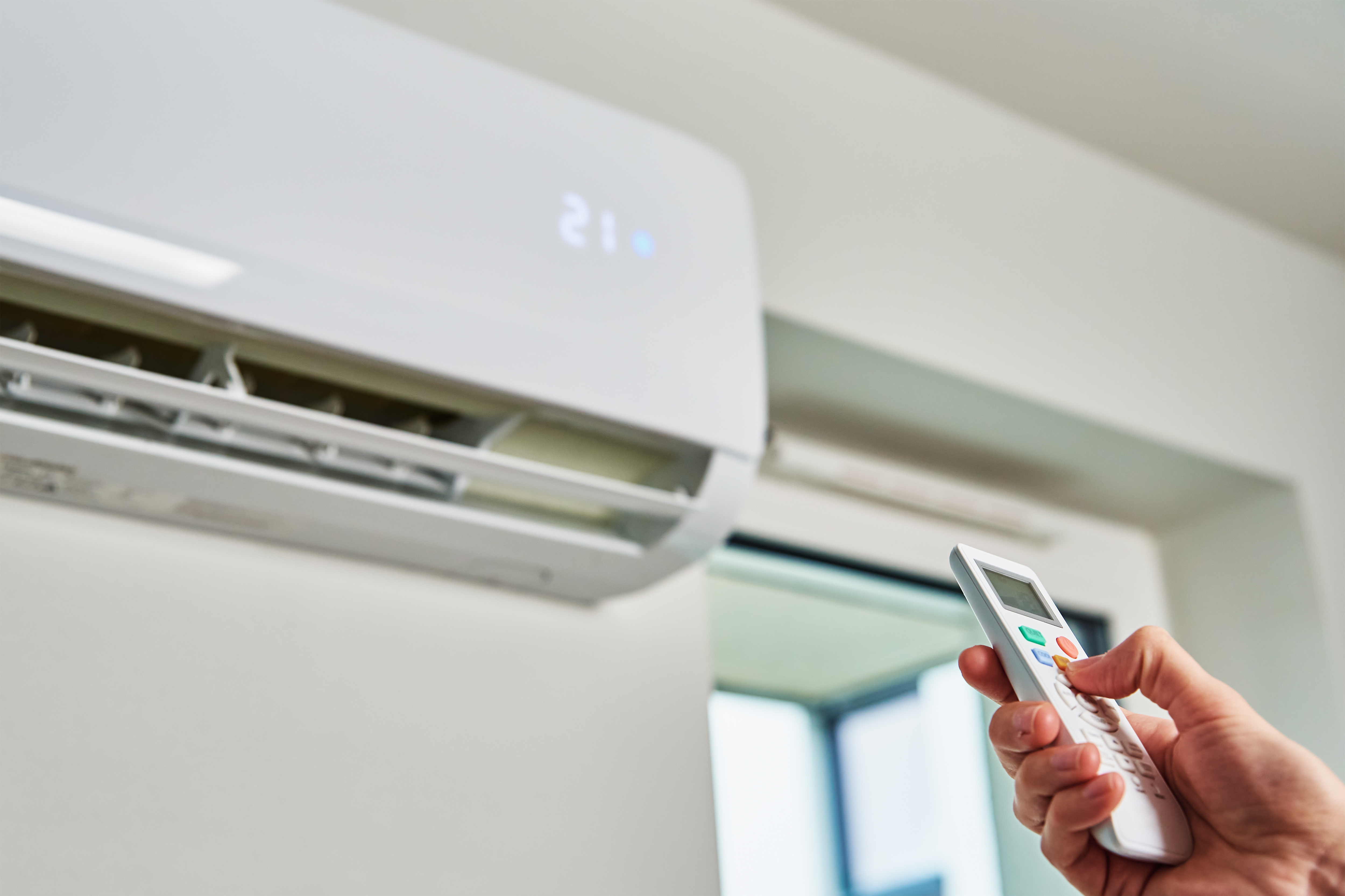
Home Energy Use
Grid edge intelligence enabled by high-frequency, high-resolution data that’s not available in the back office. Machine learning algorithms can be applied to this data to identify load profiles for home appliances, lighting, cooling, electric vehicle and other electric loads in the home. This information can be used for numerous customer and utility operations applications and programs.
-

Activity in the Home
The high-resolution data made available through Itron’s DI platform can be used to indicate the presence of someone inside a home through identification of noncyclical load usage. This information can be used to offer consumer service programs that allow parents to identify when children are home from school and, children to identify that elderly parents are active.
-
TOU/Peak Alerts
When time of use (TOU) programs are implemented, consumers can be empowered to curtail their usage during peak periods. A TOU/Peak alerts DI app can identify when high-usage appliances are active during peak price periods and approximate savings that can be achieved if usage is managed. Ultimately, DI could be used to trigger automated response to peak pricing events.
Explore the partner engagement lifecycle.
Discover development opportunities on Itron’s GenX and Distributed Intelligence platforms. Utilities and cities are in need of innovative solutions to manage energy and water resources and to empower and engage their customers and citizens. Your solution could enable them to exceed expectations.
The Itron Developer Program is designed to support your development journey at your own pace. We provide a comprehensive set of tools and resources to help you create and test your utility or smart city solutions.
Ensure your solution is ready for market. Provide a prototype, design specifications, and lab test results for final approval in preparation for a pilot or field deployment.
Field Trials
Access commercial opportunities with global go-to-market support from Itron’s sales and marketing team.
The Power of a Partnership Ecosystem
Other question?
Lorem ipsum dolor sit amet consectetur. Platea suscipit neque luctus mauris nullam in phasellus rhoncus. Vitae integer aenean volutpat at ullamcorper lectus neque luctus mauri.


Other
Resources
Find resource documents, getting started guides, and partner success stories to aid in the development process.

Itron is global.
Lorem ipsum dolor sit amet consectetur. Platea suscipit neque luctus mauris nullam in phasellus rhoncus. Vitae integer aenean volutpat at ullamcorper lectus neque luctus mauri.